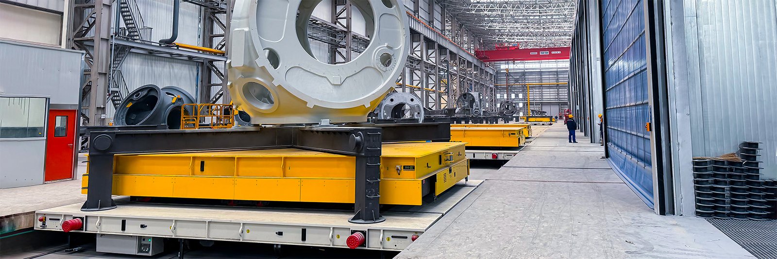
A production line can only run as smoothly as its heaviest transfer. For this wind power hub coating application, HENSEN evaluated how wind turbine hubs weighing about 130 tons moved between operating points and configured a 155-ton mother-cart RGV system with lifting sub-carts to replace or reorganize the former handling sequence.
A wind turbine hub is both heavy and tall, so its center of gravity matters throughout transfer. The coating process added another constraint: vehicles had to work around a hazardous paint environment while moving between perpendicular and parallel rail directions. A single straight-line cart could not connect the outside transfer route with the internal coating stations. The article describes the delivered concept and the engineering reasoning behind it. Buyers considering a comparable system can review HENSEN’s RGV solutions, but final capacity, tooling, navigation, safety, power, and controls must be configured from a new site survey rather than copied from this case.

Project at a Glance
- Application: wind power hub coating
- Transported load: wind turbine hubs weighing about 130 tons
- Vehicle/system: 155-ton mother-cart RGV system with lifting sub-carts
- Fleet: 12 vehicles arranged as six mother-and-sub-cart sets
- Navigation or control: high-accuracy rail alignment with a project-recorded +/-3 mm docking target
- Movement: parallel mother-cart travel outside the coating area and perpendicular sub-cart travel into the booths
- Load interface: lifting sub-carts that automatically pick and place hub carrier racks
Why This Transfer Task Was Difficult
A wind turbine hub is both heavy and tall, so its center of gravity matters throughout transfer. The coating process added another constraint: vehicles had to work around a hazardous paint environment while moving between perpendicular and parallel rail directions. A single straight-line cart could not connect the outside transfer route with the internal coating stations.
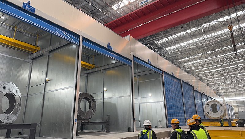
The operating environment added another layer: a coating workshop with combustible hazards, high centers of gravity, and intersecting rail directions. A vehicle selected only by rated tonnage would not address those constraints. Route geometry, wheel loads, docking, sensor visibility, stopping distance, and the way operators or production equipment interact with the load all had to be considered together.
The transfer interface was especially important. The project used lifting sub-carts that automatically pick and place hub carrier racks. That interface determines where forces enter the vehicle, how the load is restrained, how accurately the vehicle must stop, and what must happen before movement is permitted. Treating the tooling as part of the vehicle system reduces ambiguity at each station.
The HENSEN Customized Solution
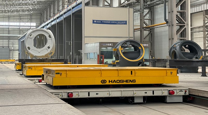
HENSEN supplied six coordinated sets, comprising six 155-ton ferry mother carts and six sub-carts. The mother vehicles traveled parallel to the coating area, while the sub-carts moved perpendicularly into the process stations and used lifting mechanisms to handle the racks. The source records a +/-3 mm alignment target, explosion-protected vehicle design, millimeter-wave radar with photoelectric switches, and automatic charging.
The selected movement concept was parallel mother-cart travel outside the coating area and perpendicular sub-cart travel into the booths. HENSEN matched that motion to the available route rather than assuming that one steering or rail arrangement would suit every site. The project used high-accuracy rail alignment with a project-recorded +/-3 mm docking target for route or station control, while coordinated mother-and-sub-cart transfer across the coating process connected vehicle movement with the production process.
Power was addressed through automatic charging configured for the vehicle fleet. Power selection is part of throughput engineering: the energy source, charging or supply method, auxiliary lifting demand, travel distance, idle time, and maintenance plan determine whether the vehicle can support the required shifts.
Load Handling and Mechanical Interface
For wind turbine hubs weighing about 130 tons, the support points and center of gravity are as important as total weight. The delivered concept used lifting sub-carts that automatically pick and place hub carrier racks. Engineers must confirm the maximum and minimum load, tare weight of racks or fixtures, load overhang, center-of-gravity range, local contact pressure, allowable deflection, and restraint method before releasing a final frame design.
Dynamic conditions also matter. Acceleration, braking, curves, side travel, lifting, rotation, or transfer across a rail joint can shift forces compared with a static load. Structural analysis, wheel-load calculation, and a defined acceptance test help verify that the vehicle, tooling, floor, and load behave as one mechanical system.
Navigation, Mobility, and Docking
This project used high-accuracy rail alignment with a project-recorded +/-3 mm docking target and parallel mother-cart travel outside the coating area and perpendicular sub-cart travel into the booths. The choice followed the route and process interface. Navigation should be evaluated against stable environmental references, rail condition, floor markings, outdoor exposure, turning space, station tolerance, and the consequences of a missed dock.
Route navigation and final positioning are not always the same requirement. A vehicle may travel accurately through the workshop yet still need a secondary fine-positioning method at a roller conveyor, furnace rail, lifting rack, turntable, or production fixture. Acceptance criteria should therefore separate path following, stopping position, alignment, and repeatability.
How the Transfer Workflow Operates
- The production system or operator confirms that wind turbine hubs weighing about 130 tons is ready for transfer.
- The vehicle receives a task and checks the required route or rail section.
- The 155-ton mother-cart RGV system with lifting sub-carts travels to the pickup point using high-accuracy rail alignment with a project-recorded +/-3 mm docking target.
- The vehicle engages the load through lifting sub-carts that automatically pick and place hub carrier racks and confirms the transfer condition.
- It moves using parallel mother-cart travel outside the coating area and perpendicular sub-cart travel into the booths, while configured safety devices monitor the operating zone.
- At the destination, the system completes final positioning and exchanges the required station signals.
- The load is released or transferred, completion is confirmed, and the vehicle becomes available for the next task, charging, or inspection.
The exact task handshake, permissive signals, timeout behavior, blocked-route response, and recovery sequence must be defined in the controls specification. These details decide whether an automatic vehicle remains useful when production conditions depart from the normal cycle.
Engineering Decisions Behind Reliable Operation
Route, Floor, and Rail Conditions
The site context was a coating workshop with combustible hazards, high centers of gravity, and intersecting rail directions. A survey should record aisle width, swept path, door openings, intersections, slopes, floor joints, drainage channels, embedded rails, curves, turntables, pedestrian areas, and temporary obstructions. Heavy wheel loads also require confirmation of floor or rail structural capacity.
For trackless vehicles, floor flatness and tire contact influence steering, vibration, and stopping. For RGVs, rail gauge, level, alignment, curve geometry, foundation, and transfer joints influence wheel loading and docking. These civil interfaces should be reviewed early because correcting them after vehicle delivery can disrupt commissioning.
Safety and Environmental Protection
A heavy-duty transfer system needs a risk-based safety concept rather than a single obstacle sensor. Typical layers can include scanners or radar, safety edges, emergency stops, audible and visual warnings, controlled speed zones, safe stopping distances, station interlocks, load-present confirmation, and access control. The final selection depends on the site risk assessment.
Environmental design must reflect a coating workshop with combustible hazards, high centers of gravity, and intersecting rail directions. Heat, moisture, dust, metal debris, paint vapor, sunlight, rain, or moving structures can affect sensors, brakes, electrical enclosures, batteries, cables, and communications. Public case information describes the project approach, but the final protection level must be documented in the delivered specification.
Power, Dispatching, and System Integration
The project power concept was automatic charging configured for the vehicle fleet. For a new system, engineers should calculate duty cycle from loaded and unloaded travel, speed profile, lift or roller use, shift length, idle time, charging opportunity, and reserve capacity. Claims of continuous operation are only meaningful when the supply and maintenance strategy are included.
The project also used coordinated mother-and-sub-cart transfer across the coating process. Integration should define task ownership, vehicle status, station readiness, traffic control, production identifiers, alarms, manual overrides, user roles, and data retention. Simulation or cycle analysis can test route conflicts and capacity before on-site commissioning.
Project Outcome and Evidence Boundary
The fleet quantity, 155-ton mother-cart rating, lifting function, and recorded alignment target come from the supplied project description. Explosion protection and safety functions must always be matched to the site’s hazardous-area classification and formally reviewed for the specific installation.
The practical value is the alignment between the transport problem and the engineering response. The vehicle capacity, motion, interface, positioning, environmental protection, and production controls were selected as a connected solution. That system fit is stronger evidence for a buyer than an isolated payload number or a broad marketing claim.
A new project should establish a baseline before estimating improvement. Useful baseline measures include current cycle time, crane or forklift waiting, labor steps, route availability, near-miss exposure, load damage, energy use, and unplanned stoppage. The proposed system can then be evaluated against agreed acceptance measures without assuming that another site’s result will repeat automatically.
When a Similar Solution Makes Sense
A comparable RGV solution may be appropriate when wind turbine hubs weighing about 130 tons moves repeatedly between defined operating points and the existing method creates waiting, difficult handoffs, restricted access, or unnecessary exposure. It is especially relevant when the load can use a repeatable support or tooling interface and the route can be controlled for automated or assisted travel.
The same concept may be unsuitable when loads have unknown support conditions, the route cannot be kept clear, floor or rail capacity is inadequate, station positions change without control, or manual intervention remains necessary at every step. In those cases, the process may need redesign, a hybrid manual-automatic approach, or comparison with another vehicle family.
Site Survey Checklist
- Maximum, minimum, and typical load weight
- Load dimensions, support points, center of gravity, overhang, and restraint
- Pickup, delivery, parking, maintenance, and charging or power-supply locations
- Trips per shift, peak takt, loading time, unloading time, and recovery allowance
- Aisle width, turning or curve geometry, doorways, intersections, and shared traffic
- Floor or rail strength, flatness, joints, slopes, contamination, and drainage
- Heat, humidity, dust, water, paint vapor, metal debris, or outdoor exposure
- Navigation references, final docking tolerance, and station handshakes
- Pedestrian controls, stopping distance, alarms, emergency access, and restricted zones
- Wireless coverage, PLC or MES/WMS interface, task source, and data requirements
- Power method, duty cycle, charging windows, and planned maintenance
- Acceptance criteria for load, motion, positioning, safety response, and availability
Implementation and Acceptance Planning
A strong implementation plan starts with a frozen route and interface definition. Layout drawings should show the vehicle envelope and the load envelope, not only the centerline. Mechanical drawings should define supports, fixtures, lift points, roller elevations, rail interfaces, or turntable geometry. Controls documents should identify every signal exchanged with production equipment.
Factory acceptance should test the configured vehicle functions with a representative load whenever practical. Site acceptance should then verify the real route, stations, communications, safety zones, manual recovery, and production handshakes. Operators and maintenance teams need training for normal operation, alarms, emergency response, inspection, and safe recovery after a stopped task.
Performance review should distinguish transport capacity from production capacity. A vehicle may complete its cycle on time while waiting for a station, door, crane, or operator. Logging task time, travel time, blocked time, charging time, and fault recovery helps the plant identify the real constraint and improve the process after commissioning.
Frequently Asked Questions
What was transported in this wind power hub coating project?
The project handled wind turbine hubs weighing about 130 tons using 155-ton mother-cart RGV system with lifting sub-carts. The load interface was lifting sub-carts that automatically pick and place hub carrier racks.
Why was a RGV selected?
The vehicle family matched the route and process: parallel mother-cart travel outside the coating area and perpendicular sub-cart travel into the booths. Final selection also considered load geometry, station interface, environmental risk, and integration rather than payload alone.
How was the vehicle guided or positioned?
The delivered approach used high-accuracy rail alignment with a project-recorded +/-3 mm docking target. Any numerical tolerance mentioned in this article is specific to the supplied project record and should be revalidated for a new site.
Can the design be reused in another factory?
The engineering logic can be reused, but the dimensions and specification should not be copied without a site survey. Load, route, floor or rail, docking, safety, power, and production controls change from plant to plant.
What information is needed for a quotation?
Provide load weight and dimensions, drawings or photos of supports, a route layout, station details, required trips or takt, floor or rail information, environmental conditions, power preference, safety rules, and system-integration requirements.
How should project performance be verified?
Agree on measurable factory and site acceptance criteria. Typical items include rated-load travel, stopping and docking, lifting or transfer function, safety response, cycle time, communication, manual recovery, charging or power behavior, and fault handling.
Conclusion
This case demonstrates how HENSEN approached wind turbine hubs weighing about 130 tons as a complete wind power hub coating logistics problem. The delivered concept combined a 155-ton mother-cart RGV system with lifting sub-carts with high-accuracy rail alignment with a project-recorded +/-3 mm docking target, lifting sub-carts that automatically pick and place hub carrier racks, and the production connection required for the site.
For additional examples, review the HENSEN Case Studies. A useful engineering discussion begins with the load drawing, route layout, station interfaces, production rhythm, and operating risks. Those facts define the solution boundary and allow a heavy-duty transfer system to be evaluated on evidence rather than assumption.