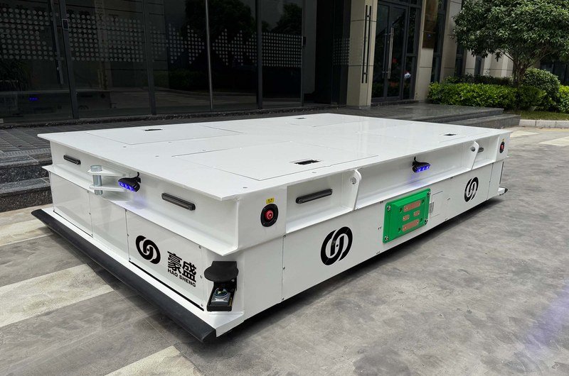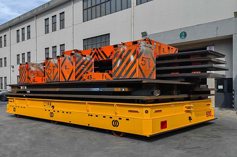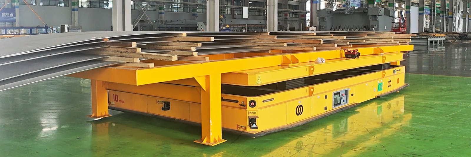
Moving steel plate between workshop zones is a deceptively complex logistics task. The load is heavy, the material footprint is large, and the transfer route often crosses production areas where cranes, equipment, operators, and other vehicles already compete for space. When each move depends on overhead lifting, manual hook-up, and repeated transfer between bays, material handling can become the constraint that limits the output of the line.
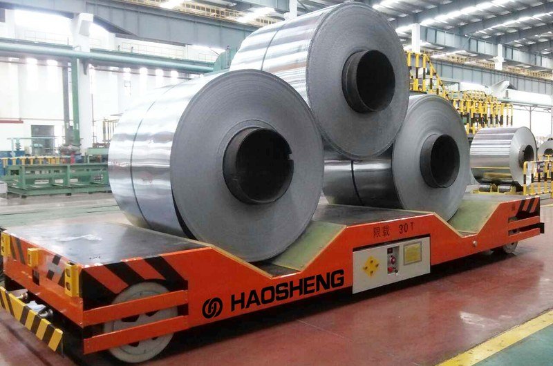
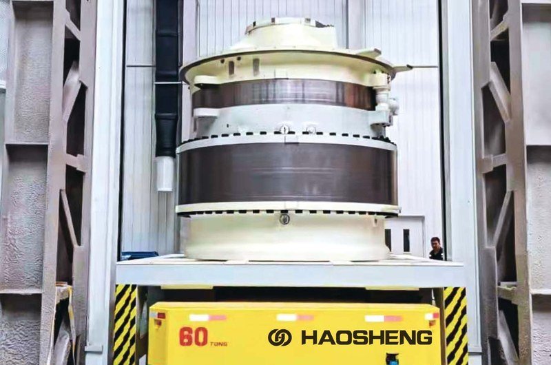
In this steel plate manufacturing project, HENSEN engineered two 10-ton heavy-duty AGVs to move dedicated steel plate racks across workshop zones. Each vehicle used an under-ride lifting structure, longitudinal and lateral travel, and 3D SLAM laser navigation. The result was a repeatable point-to-point flow that reduced dependence on overhead crane handling and separated operators from more of the load-transfer process.
This case study explains the operating problem, the engineering logic behind the solution, the workflow used on site, and the questions another steel or metal-processing plant should answer before considering a similar AGV system. Project-specific facts are identified as such. Final specifications for any new system must be designed around its actual load, route, floor, work rhythm, safety requirements, and integration needs.
Project at a Glance
- Application: steel plate transfer within a heavy-industry workshop
- Fleet: two customized heavy-duty AGVs
- Rated load in the project description: 10 tons per AGV
- Load interface: under-ride lifting AGV with dedicated steel plate carrier racks
- Motion capability: longitudinal and lateral travel for cross-bay movement
- Navigation: 3D SLAM laser navigation
- Primary objective: replace repeated crane-based transfers with automated point-to-point movement
- Recommended hensenagv.com category: Steel & Metal Processing
The Material-Handling Challenge
The plant had historically relied on overhead cranes to move steel plate. That method can be appropriate for vertical lifting and occasional handling, but it becomes less efficient when the same load must repeatedly travel between defined production zones. A crane move requires availability of the lifting equipment, a suitable attachment procedure, controlled hoisting, travel through the crane envelope, lowering, detachment, and sometimes another handoff when the material crosses into a different bay.
In this project, the limitation was not simply the lifting capacity of the crane. The broader problem was the sequence of actions surrounding every transfer. The number of plates handled per lift was limited, cross-bay changes consumed time, and the workflow depended on personnel working close to suspended or moving loads. As production demand increased, these dependencies made internal logistics a bottleneck for the production line.
Why Cross-Bay Steel Plate Transfer Is Difficult
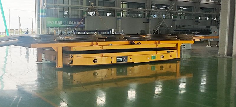
Steel plate transport combines mass, footprint, and load stability. The vehicle must support the weight while keeping the carrier rack stable, but it must also fit the available aisles and complete turns or side movements without sweeping into nearby equipment. The route may pass through doorways, bay boundaries, intersections, or shared work areas. These conditions make vehicle geometry and steering behavior as important as nominal payload.
The handling interface is another critical point. If operators still need to hook, align, or manually transfer the steel at every station, automating the travel portion alone will leave a major source of delay and exposure in place. HENSEN therefore treated the AGV and the steel plate carrier rack as one operating system rather than as unrelated pieces of equipment.
The HENSEN Heavy-Duty AGV Solution
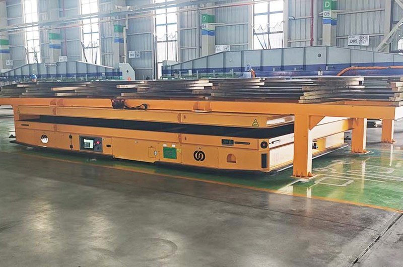
After evaluating the workshop conditions and production rhythm described for the project, HENSEN configured two 10-ton under-ride lifting AGVs. The vehicles were designed to enter below dedicated carrier racks, lift the racks from underneath, transport them along the planned route, and place them at the destination. This approach converted loading and unloading into a defined mechanical interface instead of a repeated manual rigging task.
Using two vehicles also allowed the material flow to be organized around more than one transfer task. The exact dispatching and charging strategy is not stated in the source description, so it should not be assumed. In any comparable project, fleet quantity must be verified against trip distance, loading time, unloading time, charging windows, route conflicts, required throughput, and planned maintenance availability.
Under-Ride Lifting with Dedicated Steel Plate Racks
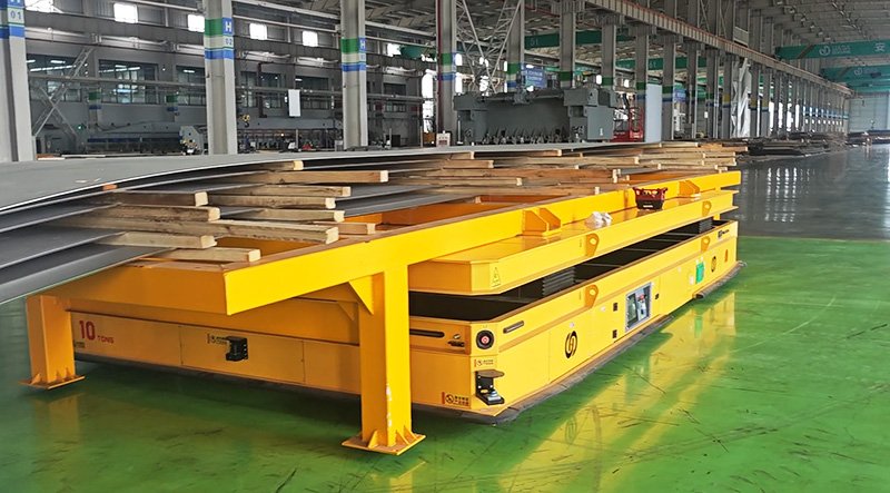
The under-ride configuration lets the AGV travel beneath a purpose-built rack when the vehicle is unloaded. Once correctly positioned, the lifting mechanism raises the rack for transport. At the destination, the AGV lowers the rack and exits. Because the rack defines the contact points and supports the steel plate, it helps standardize how the load is picked up and set down.
For this arrangement to work reliably, the rack and vehicle must be engineered together. Rack clearance, leg position, lifting stroke, load distribution, center of gravity, allowable deck deflection, and docking tolerance all affect the design. The final rack must also remain stable when it is standing without the AGV underneath it. These details are normally confirmed during site survey and mechanical interface review.
Longitudinal and Lateral Movement
Both project AGVs were configured for longitudinal and lateral movement. That capability was selected for the limited workshop passages and cross-bay transfer requirement. Side travel can reduce the need for wide turning arcs when the load or aisle geometry makes conventional forward turning impractical. It can also simplify alignment with racks or stations positioned along the side of a route.
Movement capability should not be treated as a catalog feature chosen in isolation. Steering model, wheel arrangement, tire loading, floor condition, speed, turning space, and load stability must be evaluated together. A route that looks feasible on a drawing can still fail if the actual swept path, doorway clearance, floor joints, or load overhang are not included in the analysis.
3D SLAM Laser Navigation
The AGVs used 3D SLAM laser navigation to map the workshop environment and navigate between the defined start and end points. In a suitable indoor environment, SLAM navigation can reduce the need for continuous magnetic tape or QR-code infrastructure along the floor. It also supports route planning in layouts where the vehicle must move between several fixed operating points.
However, laser navigation still depends on the environment. Stable walls, columns, machines, and other persistent vertical features help localization. Long open aisles with few features, large objects that frequently change position, reflective surfaces, dust, or blocked sensor views can affect the design. Precise final docking may also require an additional positioning method when a station demands tighter repeatability than route navigation alone can provide. The correct navigation architecture must therefore be validated against the real workshop.
How the Automated Transfer Workflow Operates
- A dedicated carrier rack is loaded with steel plate at the defined preparation point.
- The AGV receives or begins a transfer task according to the configured operating logic.
- The unloaded AGV navigates to the rack and approaches the under-ride position.
- The vehicle aligns beneath the rack and raises it using the integrated lifting mechanism.
- The AGV transports the lifted rack along the planned route, including the required cross-bay movement.
- At the destination, the AGV docks, lowers the rack onto its supports, and confirms completion.
- The AGV leaves the rack and becomes available for the next task or for charging, depending on system logic.
This sequence removes the repeated hook-and-hoist cycle from the horizontal transfer itself. It also creates a consistent material interface that can be incorporated into production planning. Actual handshakes, task confirmation, access control, and fault recovery logic should be defined during controls engineering and commissioning.
Engineering Decisions Behind a Reliable System
Load and Rack Geometry
A 10-ton rating alone does not describe the complete load case. Engineers need the maximum steel plate weight, length, width, stack height, center-of-gravity range, rack tare weight, and any uneven loading condition. The supporting structure must distribute forces into the vehicle frame and wheels without creating unstable local loads. The rack must also prevent unintended movement of the steel during acceleration, braking, lateral travel, and emergency stopping.
Route and Floor Conditions
The route survey should record clear aisle width, doorway dimensions, intersections, blind corners, floor joints, trenches, rails, slopes, surface damage, and shared pedestrian or vehicle zones. Floor strength and flatness are especially important for a heavy AGV because wheel loads can be concentrated. A site may need local floor repair, protected crossings, route segregation, or speed limits before automatic transport can operate consistently.
Safety Architecture
Reducing human exposure requires more than removing a crane task. A heavy-duty AGV system should be configured with appropriate obstacle detection, warning devices, emergency-stop access, speed management, protective fields, safe stopping distances, and station interlocks. The design must consider people approaching from the side, temporary obstructions, loads extending beyond the vehicle, and the difference between normal braking and emergency stopping. Final safety measures depend on the risk assessment and applicable site requirements.
Power, Communication, and Production Integration
Battery capacity and charging cannot be selected from vehicle tonnage alone. Engineers must calculate travel distance, cycle frequency, idle time, operating shifts, acceleration profile, auxiliary lifting loads, and charging opportunities. Communication coverage also needs to be checked across the route. Where the AGV exchanges tasks or status with a control system, the interface with MES, WMS, PLCs, workstations, doors, or production equipment should be documented before commissioning.
Project Results and Evidence Boundary
According to the project description provided for this case, overall transfer efficiency increased by 200% after the two AGVs were introduced. The same description reports that automated movement reduced human-machine crossover during the transfer process and relieved the former production bottleneck. These results are presented as project-specific outcomes from the supplied case record.
The percentage should not be interpreted as a guaranteed result for another facility. Improvement depends on the baseline method, route length, crane waiting time, number of transfers, rack preparation, vehicle availability, charging plan, traffic control, and production schedule. For a new project, the credible way to estimate value is to map the current cycle, model the proposed AGV cycle, identify constraints, and define how performance will be measured during acceptance.
The strongest evidence from this application is the fit between the problem and the engineering solution: a repetitive cross-bay steel plate flow was matched with under-ride rack handling, multidirectional movement, and map-based navigation. This system-level alignment is more useful to prospective buyers than an isolated payload figure.
When a Similar AGV Solution Makes Sense
A similar heavy-duty AGV concept may be suitable when steel plate, fabricated components, tooling, or other large loads move repeatedly between stable stations; crane waiting and cross-bay handoffs limit throughput; the load can be supported on a standardized rack; and the route can be made compatible with automated travel. It is particularly relevant when the plant wants flexible routing without adding a continuous rail system to the floor.
An AGV may be less appropriate when the route cannot be kept sufficiently clear, floor capacity is inadequate, the load changes shape unpredictably, every move has a different start and end condition, or the process still depends on extensive manual positioning. In a high-frequency fixed-route application, an RGV or rail transfer cart may deserve comparison. HENSEN evaluates both vehicle families so the selection can follow the process instead of forcing the process to fit a predetermined product.
Site Survey Checklist for Steel Plate AGV Projects
- Maximum and minimum load weight, including the carrier rack
- Steel plate and rack dimensions, overhang, center of gravity, and load restraint
- Start points, destination points, parking positions, and charging location
- Required trips per shift, peak cycle time, loading time, and unloading time
- Aisle width, turn geometry, doorway clearance, intersections, and cross-bay transitions
- Floor strength, flatness, joints, trenches, slopes, contamination, and repair history
- Pedestrian areas, forklifts, cranes, blind corners, and other shared-route risks
- Environmental factors such as dust, water, metal debris, temperature, and changing obstacles
- Navigation references, docking tolerance, and any requirement for secondary precise positioning
- Wireless coverage, system interfaces, task source, production interlocks, and data ownership
- Battery strategy, available charging windows, duty cycle, and recovery plan
- Acceptance criteria for capacity, docking, safety response, availability, and fault handling
Why HENSEN Uses a Custom Engineering Approach
Heavy-duty automated material handling rarely succeeds as an off-the-shelf purchase. Payload is only one input. Platform dimensions, frame structure, steering, navigation, lifting tooling, safety sensors, battery configuration, charging, fleet control, and production interfaces all change with the site. HENSEN develops heavy-duty AGV and RGV solutions around these operating conditions and uses project discovery to turn production requirements into a vehicle and system configuration.
For buyers reviewing alternatives, the most useful next step is to compare this application with other industrial transfer projects in the HENSEN Case Studies, then prepare a route drawing, load data, cycle requirements, and station details for engineering review. That information allows the discussion to move from a general AGV concept to a realistic solution boundary.
Frequently Asked Questions
What type of AGV was used for this steel plate project?
The project used two customized 10-ton under-ride lifting heavy-duty AGVs. They were configured for longitudinal and lateral movement and used 3D SLAM laser navigation. Dedicated racks supported the steel plate and provided the mechanical interface for automatic pickup and placement.
Why use an under-ride lifting AGV for steel plate?
An under-ride AGV can enter below a standardized carrier rack, lift it, transport it, and set it down without requiring a separate hook-up for every horizontal move. This can make station-to-station transfer more repeatable, provided the rack geometry, load distribution, docking, and safety controls are designed as part of the complete system.
Does 3D SLAM navigation require magnetic tape on the floor?
Not as a continuous route guide in the way a magnetic-guidance system does. A 3D SLAM AGV localizes against mapped environmental features. The site must still provide suitable, stable references, and some stations may use an additional precise-positioning method when the process requires it.
Can a steel plate AGV move sideways?
It can when the steering and drive architecture is designed for lateral travel. The two AGVs in this case included longitudinal and lateral movement to handle restricted passages and cross-bay transfer. The correct motion model for another plant depends on aisle width, floor quality, load shape, speed, turning space, and docking needs.
How is AGV capacity determined for a steel plant?
Capacity selection starts with the maximum combined weight of the material and carrier, but engineers also evaluate dimensions, center of gravity, dynamic forces, wheel loads, floor capacity, slope, route, cycle frequency, and safety factors. Two applications with the same nominal tonnage can require very different vehicle structures.
Can the 200% efficiency improvement be expected in another project?
No fixed percentage should be assumed. The 200% figure comes from the supplied description of this specific project. A new plant should establish its current cycle time and constraints, simulate or calculate the proposed workflow, and agree on measurable acceptance criteria before making a performance claim.
Conclusion
This project shows how steel plate transfer can be redesigned when the challenge is approached as a complete logistics system. The two 10-ton AGVs did more than replace horizontal crane travel: their under-ride lifting interface, dedicated racks, multidirectional movement, and 3D SLAM navigation created a repeatable flow between workshop zones. For another steel or metal-processing plant, the correct solution may use a different payload, steering model, navigation method, rack design, charging strategy, or fleet size. The decisive work happens before the vehicle is built: documenting the load, surveying the route, checking the floor, defining safe operation, and connecting the transfer cycle to production requirements. That is the foundation of a credible heavy-duty AGV project and the basis for a solution that can perform reliably in daily operation.