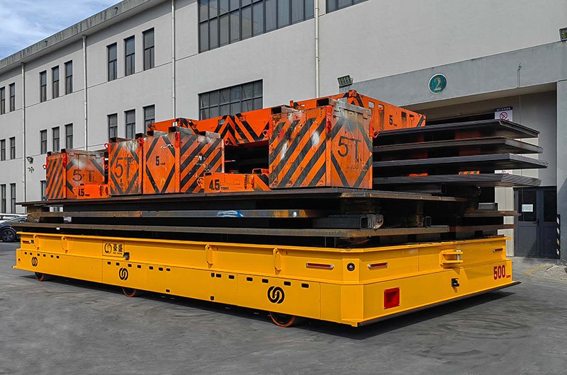
Five hundred tons is the mass of a fully loaded jumbo jet, and an ultra-heavy AGV moves it across a factory floor with nobody on board, stopping within millimeters of its target. Vehicles in this class carry wind turbine nacelles, hydropower components, transformer bodies and ship blocks — loads that until recently only moved on rented modular transporters with a crew, or not at all.
Most articles about heavy AGVs talk about what they can carry. This one is about how: the actual engineering inside a 500-ton machine. Almost nothing from a conventional AGV survives the scale-up unchanged. The wheels multiply into axle groups, the frame becomes a bridge structure, the suspension turns hydraulic, and a single drive motor becomes a synchronized team. Here is the teardown, system by system.
The First Constraint: The Floor, Not the Vehicle
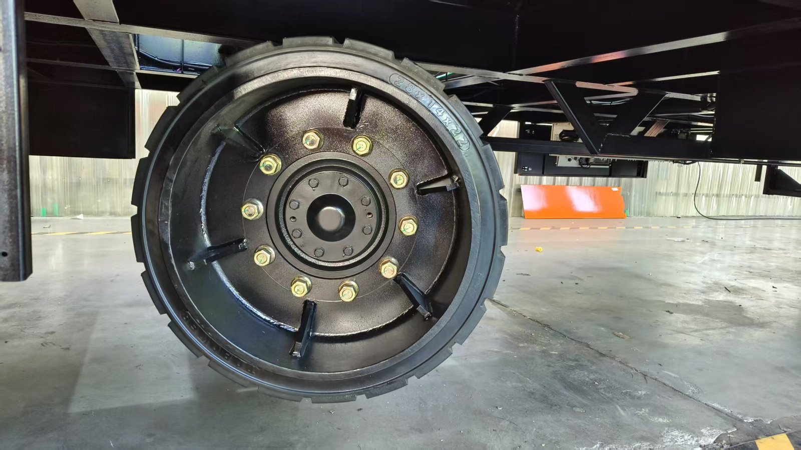
The design of an ultra-heavy AGV starts under the wheels. Heavy AGVs run on polyurethane-tired wheels, and every wheel presses its share of vehicle-plus-payload into an industrial slab that was poured to a finite bearing capacity. Ground wheel pressure is the governing design constraint of the whole vehicle: it dictates how many wheels the machine needs, how they are grouped into axles, and how the load must be shared among them.
Divide roughly 500 tons of payload plus the vehicle’s own deadweight by an allowable wheel load, and the answer is not four wheels or eight — it is wheel groups arranged in multiple axle lines along the chassis. That single calculation cascades into everything that follows: a many-wheeled vehicle needs hydraulic load sharing to keep every wheel pressing evenly, coordinated steering so all those wheels agree on the path, and synchronized traction so they pull together rather than fight each other.
The Frame: A Welded Bridge on Wheels
The chassis of a 500-ton AGV is structurally closer to a bridge span than to a vehicle frame. It is welded from Q345 steel box-beam sections — closed rectangular profiles chosen for their stiffness in both bending and torsion — into a ladder or grid structure deep enough to carry the payload between axle groups without meaningful sag.
Why the fabrication sequence matters
Welding that much steel locks residual stress into the structure, and residual stress released later means distortion — a frame that was flat in the shop and is not flat under load. Serious builders therefore anneal the complete welded frame to relieve stress, and only then machine every critical surface — axle seats, slewing-bearing mounts, cylinder pads — on a gantry machining center in a single setup. One setup means every machined face shares one reference, so wheels and cylinders meet the frame in true positions.
How stiff is stiff enough?
The working figure across heavy transfer vehicles is deflection of about L/1000 at rated load — one millimeter of sag per meter of span. On a vehicle this size, that discipline is not cosmetic: excessive flex would unload some wheel groups and overload others, defeating the load-sharing math the wheel-pressure calculation depends on. The same structural rules govern smaller vehicles too — see our AGV frame and chassis design guide for the full treatment.
Hydraulic Suspension: Making Many Wheels Share One Load
With dozens of wheels on a floor that is never perfectly flat, a rigid vehicle would ride on its three highest points while other wheels carried almost nothing. The solution is hydraulic suspension: each axle group sits on hydraulic cylinders, and cylinders are plumbed together into groups that act like a self-leveling support system.
What the cylinder groups do
Load equalization
Within a plumbed group, oil flows freely between cylinders, so every wheel in the group presses on the floor with equal force regardless of small floor irregularities. The wheel-pressure calculation from the first section only holds true because the suspension enforces it hydraulically, meter after meter.
Three-point stability
The cylinder groups are typically arranged as three (or four) virtual support points, giving the vehicle the determinate stability of a three-legged stool with the redundancy of many wheels. The load stays level and fully supported even as the vehicle crosses joints and gentle slopes in the slab.
Lifting and height control
The same cylinders raise and lower the deck to pick up loads from stands or align with stations. Where a synchronized lift under load is required, multi-cylinder synchronization is held to about ±1 mm — the load rises flat, not corner by corner.
Drive and Steering: Many Motors, One Motion
No single motor drives a 500-ton vehicle. Traction comes from multiple electric drive units distributed among the axle lines, and steering comes from powered steering-wheel units that can each rotate to any angle. Together they make an ultra-heavy vehicle omnidirectional: it can travel straight, crab sideways, move diagonally, or rotate in place around its own center — indispensable when a nacelle must enter a test stand with centimeters of clearance.
Synchronization is the real engineering
The hard problem is not producing enough torque; it is making every drive and steering unit agree. The vehicle controller continuously coordinates all wheel units so their speeds and steering angles describe one consistent motion of the whole vehicle. If the wheels disagree even slightly, they scrub — scrubbing at these wheel loads shreds polyurethane tires and loads the frame in ways it was never meant to see. Travel speed is deliberately modest: 0–20 m/min with stepless variable speed and soft start and stop, because smooth acceleration of 500 tons matters far more than top speed.
Navigation: Steering 500 Tons to the Millimeter
Ultra-heavy AGVs use the same navigation families as their smaller siblings, tuned for the scale. 3D SLAM laser navigation is the modern default: the vehicle builds and matches a laser map of the plant, needs no reflectors or floor markers, and achieves positioning accuracy of roughly ±10–15 mm. For outdoor yard segments, RTK satellite positioning takes over, and the two can hand off on a single route — how this works in detail is covered in our 3D SLAM navigation guide.
What changes at 500 tons is not the sensor but the control margin. The navigation and motion controllers plan gentle approach trajectories and long, smooth decelerations, because the kinetic energy being managed is enormous even at walking pace. Final positioning at load stations combines the navigation solution with station-side reference measurement, so the vehicle settles onto its target as a controlled, verified event.
The Control System That Holds It Together
The orchestra needs a conductor. A vehicle PLC runs the coordination loops — traction synchronization, steering geometry, suspension pressures, lift sequencing — while a 7-inch onboard touchscreen gives commissioning engineers and operators visibility into every subsystem. The vehicle offers three operating modes: fully automatic under fleet scheduling, semi-automatic for supervised moves, and manual control for maintenance and recovery. Upstream, it reports to plant systems over industrial WiFi or 5G using TCP or MQTT, taking missions from the MES or scheduling software like any other AGV — just one that happens to outweigh the building crane. Safety hardware follows the same layered stack as all heavy AGVs — 270° front and rear laser scanning, four-corner emergency stops, audible and visual warnings, electromagnetic braking — engineered with stopping margins appropriate to the mass. We dissect that stack separately in our heavy-duty AGV safety systems guide.
Proving It: Testing and Delivery
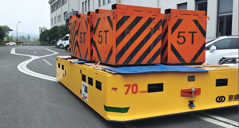
A machine like this is never delivered on faith. Before shipment, the complete vehicle is load-tested at 1.1 times rated capacity — for a 500-ton vehicle, that is a 550-ton proof load on the builder’s own floor — while frame behavior, suspension pressures, drive synchronization and braking are verified against the technical agreement. Typical delivery time from signed technical agreement to factory acceptance is about 3–4 months, and the resulting vehicle is a 10–15+ year asset.
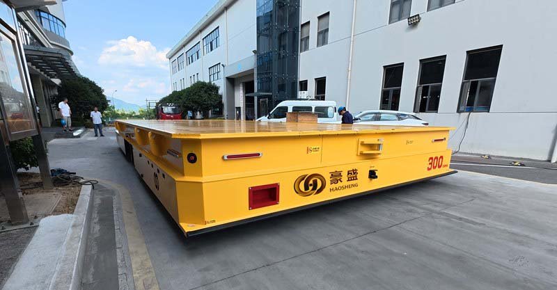
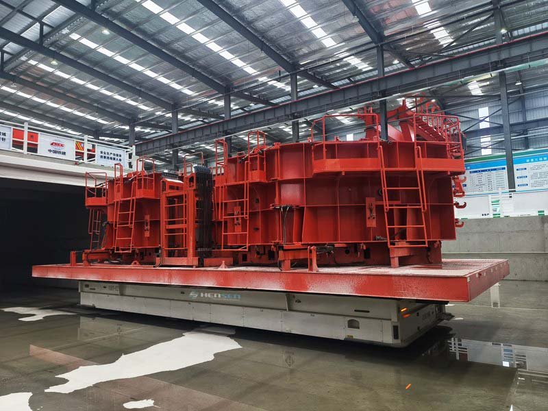
The engineering described here is proven in service, not theoretical: delivered examples include a 500-ton AGV, 300-ton AGVs carrying wind power components, and 100-ton AGVs running production sub-lines on a major hydropower project.
| Subsystem | What changes at 500 tons | Governing requirement |
| Wheels & axles | Multiple axle lines of polyurethane wheels | Floor wheel-pressure limit |
| Frame | Annealed Q345 box-beam bridge structure, gantry-machined in one setup | Deflection ≈ L/1000 at rated load |
| Suspension | Hydraulic cylinder groups, three-point support | Equal wheel loads on real floors |
| Drive & steering | Multiple synchronized drive and steering-wheel units | One consistent vehicle motion, no scrub |
| Navigation | 3D SLAM (±10–15 mm), RTK outdoors | Controlled approach and verified docking |
| Verification | 1.1× rated proof load test before shipment | Contractual factory acceptance |
HENSEN (Hangzhou Haosheng Electric Vehicle Co., Ltd.) designs and builds ultra-heavy automated transporters and rail transfer carts from 1 to 500 tons — plus heavy-duty AGVs up to 800 tons — with in-house control and scheduling software, CE marking and ISO 9001 certified manufacturing, delivered across wind power, metallurgy, hydropower and construction machinery plants worldwide. Tell us your payload, dimensions and floor conditions, and our engineers will propose an axle and suspension configuration with budget pricing.
FAQ
Q: What is the biggest design constraint on a 500-ton AGV?
A: Ground wheel pressure. The factory floor can only bear so much force per wheel, so the payload and vehicle weight must be spread across multiple axle lines of polyurethane wheels, with hydraulic suspension ensuring every wheel actually carries its calculated share.
Q: How does a 500-ton AGV steer?
A: Through multiple powered steering-wheel units, each able to rotate to any angle under coordinated control. This makes the vehicle omnidirectional — straight travel, sideways crabbing, diagonal moves and rotation in place — which is essential for positioning huge components in tight halls.
Q: How fast does an ultra-heavy AGV travel?
A: Automatic operation runs at 0–20 m/min with stepless speed control and soft start/stop. At this mass, smooth and predictable acceleration and braking matter far more than speed, and cycle times are won through elimination of cranes and waiting, not velocity.
Q: What navigation accuracy is achievable at this scale?
A: 3D SLAM laser navigation positions the vehicle to roughly ±10–15 mm without reflectors or floor markers, with RTK satellite positioning available for outdoor segments. Final docking combines navigation with station-side reference measurement for verified positioning.
Q: How is a 500-ton AGV tested before delivery?
A: With a physical proof-load test at 1.1 times rated capacity on the manufacturer’s floor, verifying frame deflection, suspension load sharing, drive synchronization, and braking against the technical agreement before factory acceptance. Typical delivery is about 3–4 months from signed agreement.
Conclusion
A 500-ton AGV is not a big version of a small robot — it is a piece of civil-scale structural and hydraulic engineering that happens to drive itself. Every major decision flows from one number: the wheel pressure the floor can accept. From there come the axle lines, the annealed box-beam frame held to L/1000, the hydraulic suspension that makes the load-sharing math real, and the synchronized drive and steering that move it all as one body. When you evaluate a builder at this scale, ask to see exactly these calculations — and the 1.1× proof-load test that proves them. Schedule a free consultation to learn more.


Leave a comment